Traffic Signal Detection
A RC Car with Stop Signal Detection
By Yibang Xiao (YX455) and Hao Jing (HJ399).
Demonstration Video
Introduction
Computer vision has been a hot topic due to its extensive use in a wide range of applications especially in machine learning and deep learning models. Autonomous cars are another big topic in the technology field nowadays. As a result, our team design a robot that will be able to detect some simple objects on the road such as stop signs, red lights and etc. The robot will basically have two modes. One mode is manually controlled mode,called m1 mode. The user will be able to manipulate the robot by remote ASSH orVNCB or by a web controlling feature with WIFI. The robot can be controlled by the keyboard. ‘W’ key can let the robot go forward, ‘X’ is backward, ‘A’ turn left, ‘D’ turn right, and ‘S’ to stop. The key ‘I’ will speed up the robot and key ‘j’ will slow down the robot. The robot will have a variety of speeds and it will be able to speed up as well as slow down as desired. In the second mode, m2 mode, we will design a Line-Tracing Self-Driving Car. The robot will recognize the black line on the white cardboard automatically and moving along the line. We will also implement a camera on the front of the robot and transmit the video to our laptop in realtime so that we can see whatever has been seen by the robot. When it ‘sees’ a stop sign, it will stop for 3 seconds and then resume. Two modes can be switched at anytime and there will be an emergency stop implemented in case there is something unanticipated occurs.
Project Objective:
- Control the robot manually by keyboard or remote control (web, VNC, SSH)
- Autonomous tracing the black line.
- The robot will "learn" some traffic rules (stop sign) and take the correct action.
Design and Testing
Motor Board Connection
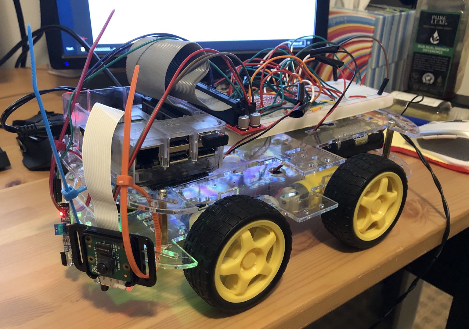
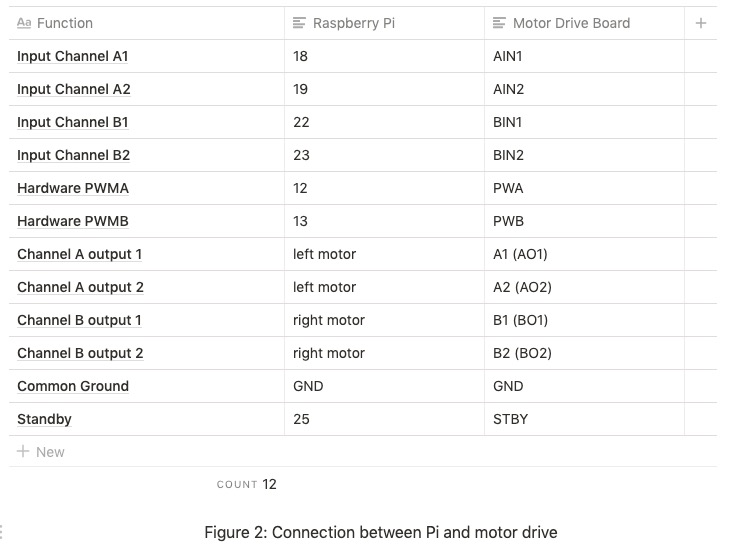
In this project, there are mainly two mode of our robot car and the first step is to buy some necessary parts from Amazon. These parts including the robot base (which includes four motors), two TB6612FN motor drive chip and two IR Infrared Obstacle Avoidance Sensors. In addition, the Raspberry Pi and the Pi camera V2 is provided by the Professor. After we assemble the robot, we plan to read the data sheet to wire the pins between the Pi and the motor drive board. According to the data sheet for TB6612FN motor drive board, the AIN, BIN pins are input channels and AO, BO are cons-pounding output channels. Each of the channel has a hardware PWM named PWMA and PWMB. The Vcc is the small signal supply and Vm is the motor supply. There is one more STBY pin need to be connected to logic high in order to make the motors rolling, otherwise, the motor will also be in standby mode. The Vcc is connected to logic high(3.3VB and ground all the GND pins.
Our connections are as shown in the Figure 2: (Raspberry Pi pin number is based on BCM mode)
Note: On the motor drive board, two AO1 and AO2 pins are denoted as A1 and A2 and, similarly, BO1 and BO2 are denoted as B1 and B2.)
We first used two motor drive boards to control four motors in total, but it turns out to be working with a single motor drive board. One thing worth to be mentioned is that we first powered VM pin with Raspberry Pi 5V output, it works fine for two motors at a time, but the pi will reboot if a third motor is connected to the motor board. After discussed with the professor, we found out the reason is that the current motor requested exceeded the pi's maximum current output. We fixed the problem by powering the motor board with four AAA batteries, that is 6V voltage supply.
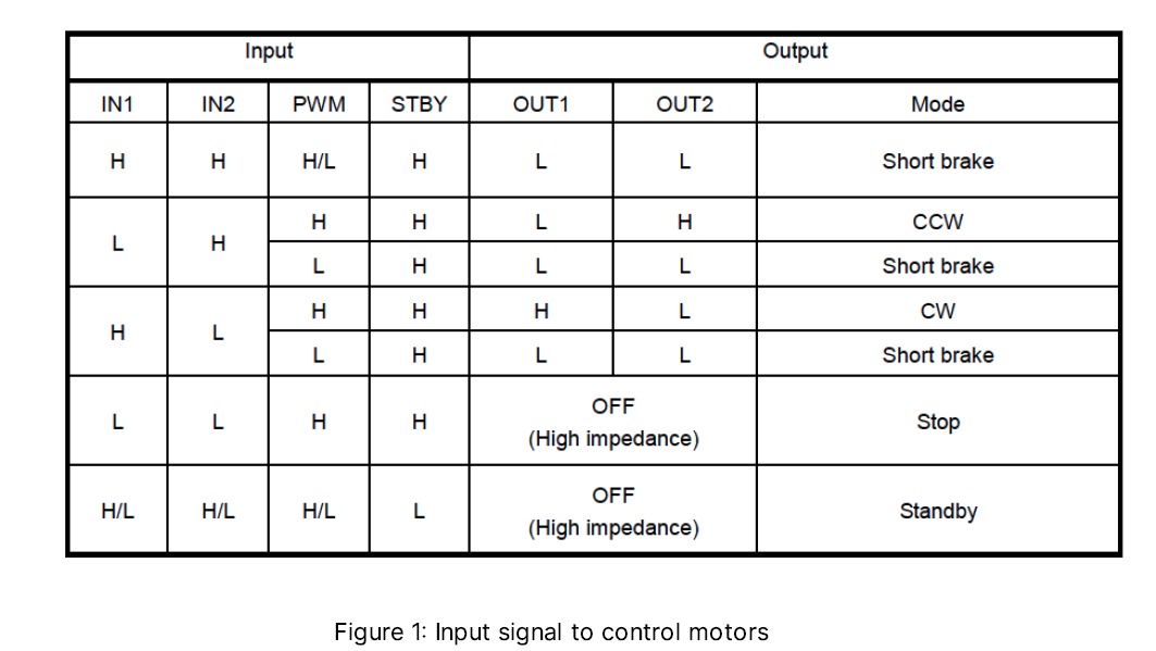
The motor is also connected according to the data sheets as shown in Figure 1.
The next step is to write a program to control all the motors as we desired. Since it is a relatively complex system, we decide to write a multithread program to control all different parts together. In order to create a thread we need to write a function for its functionality and give a name for that thread then start the specific thread (shown in main.py at line 467
Keyboard Pressed Thread
Since we would like to read from keyboard input one character a time without an enter key, most of the input function would not meet our requirements. We search on online and find a Github repo by jasonrdsouza to fix this problem (https://gist.github.com/jasonrdsouza/1901709). Basically, the code change some settings for the terminal to accept one character per time. Then a write a keyboard pressed thread to keep reading from the keyboard. There are totally 9 keys used in our case. Key 'w', 'x', 'a', 'd' are used for forward, backward, left and right turn respectively. The key 'i' is to speed up and 'j' is used to slow down. The key 'm' is used to switch the modes, 's' is used to stop all the motors and 'c' is used to quit the program. We used dictionaries to keep all the current data. There ECE 5725 Final project 3 are two categories: speed and mode. The speed has 5 different levels and the mode has three different levels ('0' means stop, '1' means forward and '2' means backward). Once 'w' or 's' or 'x' is pressed, we set the mode correspondingly and if 'i' or 'j' is pressed, the speed mode will increase or decrease 1 which mean a 20% duty cycle of the motor supply. In order to protect motors, we set the protection (stop the motors for 1 second) to avoid motors simultaneously switch from clockwise to counter-clockwise rotation. While we exit the program, we have to close the motor channel and cleanup the GPIO ports to avoid future conflict warnings.
Motor Control Thread
For the motor control thread, we first have to create the channels for the motors. This is a python 3 library provided online which can be found at (https://github.com/gavinlyonsrepo/RpiMotorLib/blob/master/Documentation/TB6612FNG_DC.md). Since we have two sides of motors, two dictionaries are used to separately record the current data, however, the logic for both sides motor control are very similar.
We first have to check the current mode (m1 for manually control and m2 for autonomous). If it is m1 mode, we check wether there is a turn indictor. If there is a turn need to be finished, we perform the turn first by stopping the motor on the turning side. For example, if the robot is going to turn left, we stop the left motors while keep the same speed on the right to perform a left turn and vice versa. Then we read the data in dictionary and to sent the desired signals to the motor. For example, if the mode is '1' and the speed is '4', then we send motor to be forward at a duty cycle of 80. If the mode is '0' which means stop mode, we stop all the motors until further instructions.
If it is in m2 autonomous mode, we have to read from the IR sensor to trace the black line. We used GPIO port 16 and 17 to read the results from the IR sensors. A result of '0' indicated a white is detected and a result of '1' meant a black is detected. Since our four-wheel robot is relatively hard to turn, we design a speed-up turning to help the robot to make turns. We assemble one IR sensor on the front-left and the other on the front-right. If both of them have a result of 0, then the robot keep the same speed. Once one side reads a '1', we stop the same side motors as well as speedup the other side motors to help it turning. The robot will keep checking wether there is a red light indicator and if there is a red light detected (more detail will introduce later), the robot will stop for 3 seconds.
Stop Sign Detection
We implemented the Stop Sign Detection module in C++ with the help of OpenCV. OpenCV has built-in function of the template matching algorithms. In our project, we use the cross correlation algorithm. This algorithm (we will write as CC below) can process the images in these way:
- Firstly, it will take an input image as a template (usually has smaller size than the image sets), which is the target object we need to find.
- Secondly, it will load the image sets and doing CC algorithm on them
- Once finished, the program gets an integer result and move the template to right by one pixel to do next CC algorithm.
- Finally, we compare the several integer results and find the maximum one. That pixel is the object we found.
However, due to the noise from the image background, we have to use some image processing techniques to reduce the effect of the noise and improve the accuracy of object detection. Here is our step-by-step methods:
- We use OpenCV video capture function to read the frames and store them in Matrix variable
- The first step of image processing is to reduce the size of the frame from 1920x1080 to 256x192. The reason is that we want to reduce the pixel-by pixel operation and focus less on the background noise.
- The second step is to blur the frame images by blurring index of 3 or 6. This step can also reduce the noise from the background and improve the accuracy.
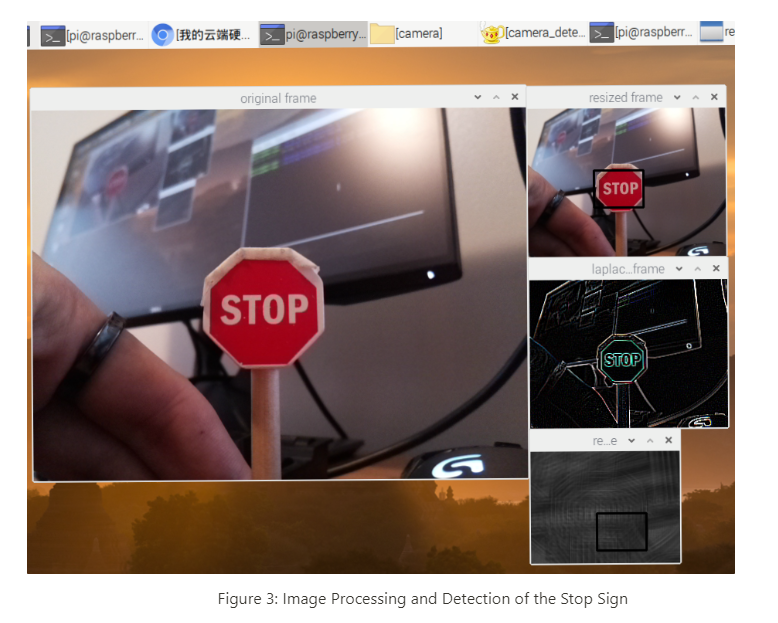
- The third step is to apply Laplacian filter on the images. Laplacian filter is one of the famous edge detection algorithm in the image processing. It is worth mentioning that if the program has Laplacian filter, the input matrix should in the CV_8U or CV_64F data type. We recommend to use CV_8U because you will get a clean black background on the image shown in Figure "四个窗口的图". Otherwise you will get the image with lots of noise pixel which will decrease the detection accuracy.
- The final step is to input our template and frames into a function called matchTemplate function and set it as CV_TM_CCORR_NORMED. This function will record all integer value and assemble them to a matrix type and output it to the result frames.
- We use minMaxLoc function to record the maximum value and the location of maximum value on the image.
- If the maximum value is larger than the threshold value, we draw a rectangle on the image based on the location of maximum value and the size of the template to tell the users that the program has found the object. In the meanwhile, this C++ program will execute an C program to send information to the FIFO to tell the main program to stop the motors. This part will be described in details in the Communication Section.
- All image processing progress are written as a sperate function and use pointer to pass the image arguments to each of them. This method can make the code look clean and organized.
We spent four days on developing the OpenCV module. During the development, we meet some problems and here are the solution we found to fix them:
- In the Laplacian Filter part, as we mentioned before, use CV_8U data type can avoid the negative data type and improve the accuracy.
- If the video capture program cannot be open in the second time, adding capture.relase() might be helpful.
- Before start the video capture and video frames processing, we have to do the same process progress on the input template: resizing, blurring, applying Laplacian Filter with CV_8U type. This can improve the detection accuracy.
- When compiling the OpenCV C++ program, it is easier and time-saving to use CMake from Linux. Firstly we can create a file called CMakeLists (case sensitive) by any text editor and type in the following commands. "camera_detection" can be replaced by your program name. After that, in the terminal, type the command "cmake ." to compile this CMakeLists file. Then every time you modify the code, you just need re-type "make" command to compile it and "./camera_detection" to run it.
Web Control Module
Raspberry Pi can be used as a web server by using a popular web server application called "Apache". On its own, Apache can serve the HTML files over HTTP, and with additional modules can serve dynamic web pages using the scripting languages such as PHP. Firstly, with the help of documents from Raspberry Pi Website, we installed the Apache on our Pi and put the index.html file and other corresponding PHP files in the directory of "/var/www/html/"
We write our home page with seven functional buttons in HTML. Each button will be linked to the corresponding separate PHP file. For example, the button named "Turn Left" is linked with the PHP file called "a_control.php". In the PHP file, it will echo a message to show that "Turn Left" button has been successfully pressed. Then this file will open the cv_fifo in write mode and use the fwrite function to write string 'a' into the cv_fifo. Then it will echo another message to show the string has been successfully sent.
To control the car from the website, the thing needed is typing the "http://ip_address" from any browser in any device connected to the same Wi-Fi with the Pi.
At the beginning, our buttons do not have any response after clicking. The reason is that we assign the button as 'button' type. To link the PHP file, the button should have the type of 'submit'. However, the negative side of using submit type is that every time we press the button, a new page will be open on the browser. The user has to hit the go back button of the browser to do other controls.
Program Communication
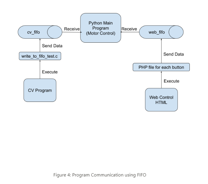
In our project, we used Python to write our main program to control the motors, C++ to write our CV object detection program, HTML and PHP to implement the Web Control Module. How to connect them and manage the communication becomes significant. Our method is using the FIFO, which is the named pipe in Operating System. Here is the diagram of the communication between each programs.
The overal program communication diagram is shown in Figure 4. For the C++ Object Detection program and Python main program, we created a thread in the main program which can keep reading the information from the FIFO called cv_fifo. If this thread receives any data from the fifo, which means the CV program detects the stop sign, it will raise the cv_flag to tell the motor control thread to stop the motors for three seconds. After that, this reading-fifo thread will sleep for 6 seconds to ignore the following detection. This is the receiver side of the cv_fifo. For the transmitter side, the C++ Object Detection program, as we mentioned before, it will show a rectangular box on the image after detecting the stop sign. In the meanwhile, it will send a shell command which will execute an executable file called "a.out". The file "a.out" is the result of executing the file called "write_to_fifo_test.c". This is a simple C program which can send one string to the cv_fifo. You can see the details of the code in the code appendix. We used the command "cc write_to_fifo_test.c" to execute this C file and generate the "a,out" file.
For the HTML and PHP Web Control part, we also created a thread in the mian Python program which keeps reading the input from the FIFO called "web_control_fifo". We wrote the action of each button in the separate PHP files and each PHP file can send corresponding strings to the “web_control_fifo”. For example, if we press "Forward" button, the PHP called "w_control.php" will send a string 'w' to the fifo. When the Python main program gets data from this fifo, it will recognize that the string is 'w' and raise the signal for moving forward to the motors.
Before using FIFO, we searched some methods about the communication between Python and C++ program. Most of them are using 'Boost' or 'Ctype' wrapper. It is far more complex than the FIFO method. However, the cost of using FIFO is that it increases the hierarchy of the program file system. Therefore, the developer should carefully manage these program files.
Some problems and the solutions we used:First, use 'mkfifo' to create the FIFO files. Secondly, at the beginning, our FIFO does not work. We found that after creating the FIFO, we should change its permission by the command "chmod a+rw /home/pi/fifo_file"
Result
Our project meets all the requirements in the proposal:
- The car can be controlled from the keyboard: 'w' (Forward), 'x' (Backward), 's' (Stop), 'a' (Turn Left), 'd' (Turn Right), 'i' (Speed Up), 'j' (Speed Down), and 'm' (Switch the Mode).
- In M1 mode, our RC car can be drove in five different speed: 20%, 40%, 60%, 80%, and 100% of the duty cycle. If the user press 'x' (Backward) when the car is moving forward, the car will stop for 0.5 second and then go backward to prevent the motor short circuit.
- In M1 mode, our RC car can be successfully controlled by the website through Wi-Fi.
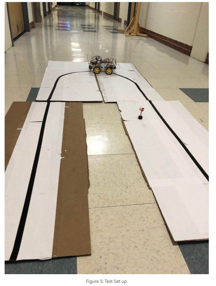
- In M2 mode, the car can trace the single black line on the white cardboard with two IR sensors and make a U turn either from right or left. Sometimes it will fail the U turn because there is a gap between the cardboard. The IR sensors read the 'black' from the gap at the same time. But most of the time, the line-tracing function can be performed successfully.
- In M2 mode, the car can detect the stop sign, stop the motors for three seconds, and restart to keep moving forward on the line. Sometimes the car stops for three seconds even there is no stop sign. The reason is the background noise. If we set up the threshold value properly, the car can stop only at the time it detects the stop sign.
- We implemented the CV part and Web Control part on schedule, but we met problems on the short circuit problem when driving the four motors and the implementation of communication between these programs. Therefore, the Motor Control part and the whole project schedule was lagged behind. We adjusted our demo date from Thursday, Dec.5th to Tuesday, Dec.10th to solve these problems.
Conclusions
Our robot can perform as we desired overall. In the manual mode, the robot can go forward, backward, left turns and right turns with 5 different speeds. Do not try to power the motor board from the Raspberry Pi and use batteries to power them! In the autonomous mode, the robot will be able to trace the black line and stop when a stop sign is detected in most of time. As we discussed earlier, these cameras are very sensitive to different lighting conditions as well as surroundings. Our project reached our goal with a good performance overall.
Future Work
Although our robot meet the requirements as we desired, there are many improvements we can do if we have more time on this project.
First of all, we can use the V2 camera instead of IR sensors to let the robot trace the black line since we already have cameras on our robot and the IR sensors are relatively unstable and the performance is affected greatly by lighting conditions and its position. However, one disadvantage of this idea is that will introduce some image processing which means will increase the computing burden on the real time system which might affect the performance overall.
Another thing is that our stop detection algorithm are not always correct. It can be affected by the lighting conditions as well as the surroundings. We might try to modify the algorithm to further improve the accuracy. We also can add more features to the robot, for instance, we can let the robot be able to detect more traffic signs to make it more intelligent.
Figures
Work Distribution
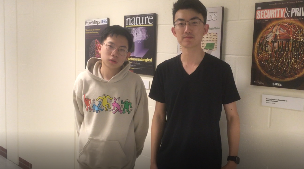
Project group picture

Yibang Xiao
yx455@cornell.edu
Implemeted and tested the CV module and programs FIFO communication.

Hao Jing
hj399@cornell.edu
Implemented and tested the motors and line-tracing.
Parts List
- Raspberry Pi $35.00
- 4-AAA-Battery Rack - Provided from Lab
- Raspberry Pi Camera V2 - Provided from Lab
- TB6612FNG Motor Driver Chip - $5.99
- IR Infred Sensors - $2.00
- SparkFun Pi Wedge BOB - 13717 - $10.95
- EMOZNY 4 Wheel 2 Layer Robot Smart Car Chassis Kits - $17.99
Total: $71.93
References
PiCamera DocumentGithub Keyboard Press Repo
Github Motor Drive Board Liabary
Motor Board Data-sheet
PHP Tutorial
HTML Tutorial
OpenCV Template Matching
Python Read From FIFO
Setting up an Apache Web Server on a Raspberry Pi